Shanghai Beizhi Electronic Technology Co., Ltd/Shanghai Biaozhi Electronic Technology Co., Ltd.
Search

Product Center


Range coverage 8000g~10000g
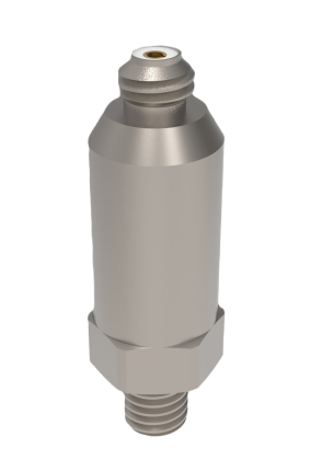
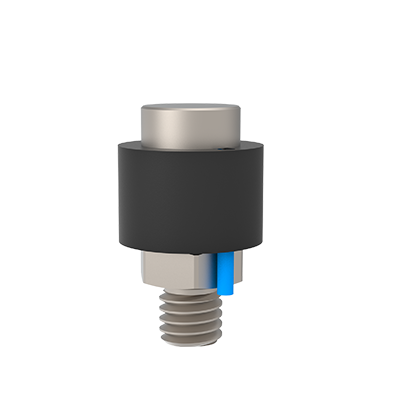
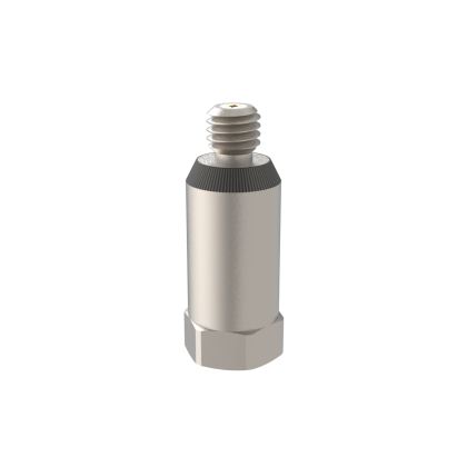
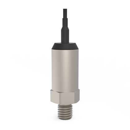
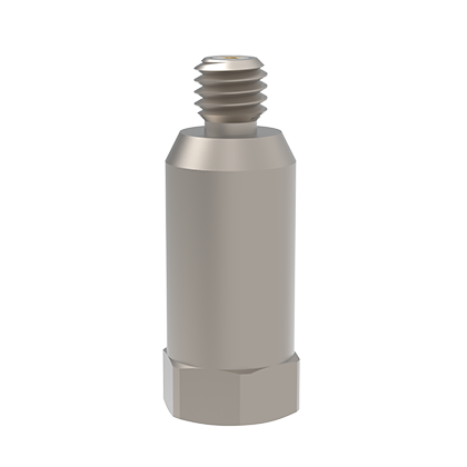
The structural form consists of installation (screws/integral bolts), output (connector/integral cable)
As well as the combination of the housing to the signal ground (insulated/non-insulated) forming different types for users to choose from
Adopts a special connection structure to achieve stable high-frequency response with ground insulation
| Model (High-end) | J21120 | J22102 | J21102 | J21100 | J21123 | J22103 | J21107 | J21103 | J21104 | J21105 | J21106 | J20210 | |
| Feature Description | Non-insulated, M5 output M5 Screw Hole Installation | Non-insulated, M5 output Connecting Rod Installation Bolts | Ground insulation, M5 nozzle output M5 Screw Hole Installation | Ground insulation, M5 output Connecting Rod Installation Bolts | Ground insulation, integrated cable output Connecting Rod Installation Bolts | ||||||||
| Dimensions mm (Hex x Height) | 11x20 | 11x20 | 9x25 | 9x25 | 10x23 | 10x23 | 10.5x30 | 10.5x30 | 10.6x26 | 10.6x26 | 10.6x26 | 9.2x18 | |
| Sensitivity (pC/g) | 1 | 2 | 0.5 | 1 | 1 | 2 | 0.5 | 1 | 1 | 0.5 | 0.3 | 0.06 | |
| Measurement Range (g peak) | ±8000 | ±7500 | ±50000 | ±25000 | ±15000 | ±7500 | ±50000 | ±25000 | ±25000 | ±50000 | ±80000 | ±100000 | |
| Amplitude Linearity (Full Scale) | ±2% | ±1% | ±3% | ±2% | ±2% | ±1% | ±3% | ±2% | ±3% | ±3% | ±5% | ±10% | |
| Frequency Range | ±5%(Hz~kHz) | 3~10 | 3~12 | 3~10 | 3~11 | 3~10 | 3~10 | 3~12 | 3~11 | 3~11 | 3~12 | 3~12 | 3~12 |
| ±10%(Hz~kHz) | 2~11 | 2~13 | 2~11 | 2~12 | 2~11 | 2~11 | 2~13 | 2~12 | 2~12 | 2~13 | 2~13 | 2~13 | |
| Installation Resonant Frequency (kHz) | ≥60 | ≥45 | ≥65 | ≥65 | ≥50 | ≥45 | ≥50 | ≥50 | ≥50 | ≥50 | ≥50 | ≥60 | |
| Transverse sensitivity | ≤5% | ||||||||||||
| Core Capacitance (pF) | 350 | 300 | 850 | 850 | 850 | 850 | 850 | 300 | 300 | 180 | 180 | 180 | |
| Core Insulation Resistance (Ω) | ≥ 1x10¹¹ | ||||||||||||
| Install Insulation Resistance | —— | —— | —— | —— | ≥1x10⁸ | ≥1x10⁸ | ≥1x10⁸ | ≥1x10⁸ | ≥1x10⁸ | ≥1x10⁸ | ≥1x10⁸ | ≥1x10⁸ | |
| Maximum Withstand Acceleration Value (g peak) | —— | 10000 | —— | —— | —— | 10000 | —— | —— | —— | —— | —— | —— | |
| Maximum Withstand Impact Value (g peak) | 30000 | 20000 | 70000 | 35000 | 35000 | 12000 | 70000 | 35000 | 35000 | 70000 | 90000 | 110000 | |
| Operating Temperature (°C) | -50~230 | ||||||||||||
| Sealing Form | Laser Welding | ||||||||||||
| Sensitive Materials | Piezoelectric Ceramic/Shear | ||||||||||||
| Case material | Stainless Steel | Stainless Steel | |||||||||||
| Sensor Installation Method | M5 threaded hole | M5 or M6 integrated bolts optional | M5 threaded hole | M5 or M6 integrated bolts optional | |||||||||
| Weight (grams) | 8.2 | 8.6 | 7 | 7 | 6.3 | 6.3 | 13 | 13 | 13 | 13 | 13 | 9 | |
| Sensor Output Format | M5 Top Output | Top Ribbon Cable | |||||||||||
| Cable end connector type | M5—M5 (511xx11); Integrated cable + M5 (5--xx11) | ||||||||||||
Common Cable Options (Cable Description/Model) | *M5 Connector Output: M5—M5 connectors at both ends of the cable: Φ2mm PVC cable (5111111); Φ2mm TPV cable (5113811); Φ2mm PTFE high-temperature cable (5111211) *Integrated cable output: Connectors at both ends of the cable. Integrated cable—M5: Φ2mm PTFE high-temperature cable (5001211); Φ1.6mm PTFE high-temperature cable (5002111) | ||||||||||||
| Standard Attachments | ① Standard: 1-meter coaxial PVC cable (output M5 connector), integrated 0.5-meter coaxial high-temperature cable (integrated cable output); ② Factory calibration report | ||||||||||||
| * Frequency Range: The low-frequency cutoff of charge output sensors depends on the low-frequency cutoff (high-pass filter) set by the charge amplifier | |||||||||||||